
OMIOCNC Home Switch (Limit Switch) – Function & Troubleshooting Guide

What Is a Home Switch?

The component labeled as "Limit Switch" on OMIOCNC machines is actually a Home Switch. It is used to determine the origin of the mechanical coordinate system. Its primary function is to let the machine know its current position, so homing (returning to the origin) must be performed before every job to ensure accurate positioning.

Factory Testing & Important Notes

Every machine is thoroughly tested before shipment. If the machine does not respond normally, you can reinstall the software and settings files. After completing the setup, do not make any additional adjustments to Mach3.

Important: If you have two machines that are not exactly the same model and were not purchased at the same time, do not use the same computer to control both. Different models or machines from different production batches require different Mach3 configurations.

Why the Home Switch Doesn't Work – Three Steps to Check

If the homing function............
Read more

Recommended Ventilation & Coolant Guidelines for X8-2200L & X8-2200EPL CNC Routers

Recommended Ventilation & Coolant Guidelines for X8-2200L & X8-2200EPL CNC Routers

This series consists of desktop CNC routers equipped with water-cooled spindles. The X8-2200L connects to a computer via USB, while the X8-2200EPL uses a built-in standalone offline controller. Below are the recommended ventilation, cooling, and dust collection specifications for indoor or school laboratory environments.

1. General Room Ventilation

  • Temperature: Maintain 18–25 °C; avoid exceeding 30 °C.
  • Humidity: Maintain 40–70% RH; prevent condensation.
  • Clearance: Leave at least 30 cm (12 inches) of space around the machine to ensure adequate airflow.
  • Air Exchange: Provide 6–10 air changes per hour (ACH) in the room.

2. Spindle Cooling (Water-Cooled)

  • Coolant: Use clean deionized or distilled water mixed with a corrosion inhibitor. Replace............
Read more

How to Use the Z-Probe (Auto Tool Zero) – Step-by-Step Guide

Using the Z-Probe (Auto Tool Zero Device)

When machining flat plate materials, the Z-probe (also called an auto tool zero device or touch plate) helps you perform Z-axis tool setting quickly and conveniently. However, you must strictly follow the operating steps below; otherwise, the probe or the cutting tool may be damaged.

Step-by-Step Instructions

  1. Insert the Z-probe and measure its thickness.
    Plug in the Z-probe cable. Measure the actual thickness of the touch plate using a caliper, and enter that thickness value into MACH3 (in the appropriate settings field).
  2. Test the Z-probe (perform this test every time before actual use).
    Turn on the POWER switch. Clear the X, Y, and Z axes to zero. Click the "Auto Tool Zero" button in the software interface. The Z-axis will slowly move downward. Briefly touch the metal clip to the surface of the touch plate — the Z-axis should stop moving down and then rise by 10 mm. This confirms the probe is working............
Read more

OMIOCNC EPL Offline Controller Parameter Definition Guide

OMIOCNC Offline Controller Parameter Definition Guide

This document defines all editable parameters for the OMIOCNC offline controller. The parameter file is fully editable but must follow the formatting rules below. Each parameter has a predefined default value and a valid range — please stay within the specified range. If you are unsure about a parameter's purpose, keep the default value.

Parameter File Editing Rules

  • Only one parameter per line.
  • Format: #parameter_number=value. The # must be the very first character on the line, followed immediately by the parameter number, then =, then the value.
  • Any explanatory text after the value assignment is optional and unrestricted.
  • Each parameter has a defined assignment range — strictly follow the specified range.
  • Each parameter comes with a preset default value. Keep the default............
Read more

How to Troubleshoot the WSJ‑M3 Control Handle

How to Troubleshoot the WSJ‑M3 Control Handle in Mach3

This guide walks you through the most common fixes for the WSJ‑M3 wireless control handle. Follow the steps in order.

Important Prerequisite

The WSJ‑M3 control handle only works when the Mach3 software is already running on your computer. If the handle does not function properly, proceed with the steps below.

1. Replace the Batteries

Install fresh AA batteries (2 pieces) in the WSJ‑M3 handle. Low battery power is the most common cause of intermittent or completely unresponsive behavior. After replacing, turn the handle back on.

2. Check Complete Installation of Mach3 Plugins and Macro Files

Many users only copy ShuttlePro.dll but forget the macro files, causing some buttons on the handle to stop working. Please verify both items below:

2.1 Check the Plugin File............

Read more

How to Adjust the Spindle Height When the Tool Cannot Reach the Material

Spindle Height Adjustment for Thin Materials

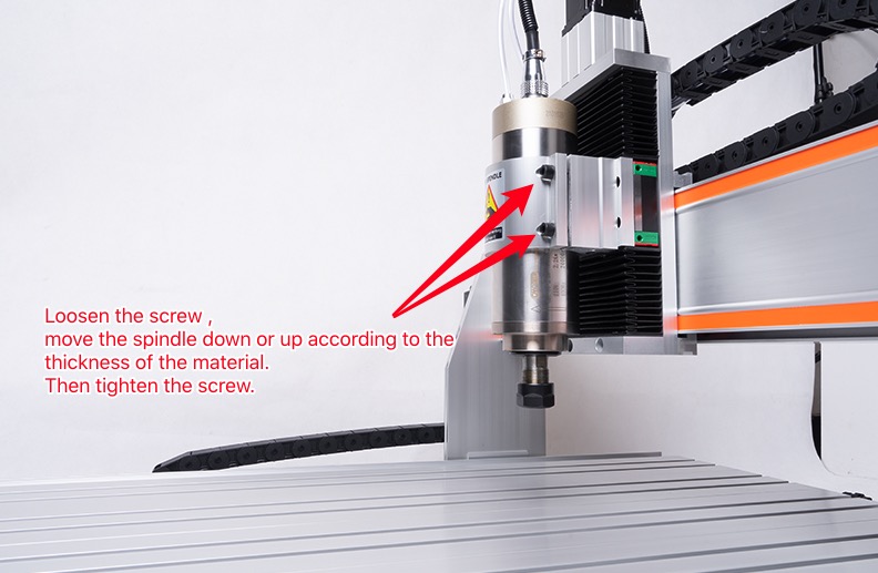
When working with thin materials, the spindle tool may not reach the workpiece surface. There are two easy solutions:

  • Lower the spindle: Loosen the screws on the spindle mount, slide the spindle downward until the tool tip contacts the material surface, then retighten the screws.
  • Add a sacrificial worktable: Place a flat plastic board (such as an acrylic sheet) underneath the material. This raises the workpiece so the tool can reach it, and also protects the machine table from accidental cuts.

Spindle Height Adjustment for Thick Materials

For thicker materials, simply lower the spindle by loosening its mounting screws and moving it downward until the tool reaches the material. No additional support board is usually needed, but always check that the tool has sufficient clearance above the workpiece............

Read more

How to Prevent Milling Cutter Damage

How to Prevent Milling Cutter Damage?

Maintaining your milling cutters is essential for achieving high-quality results and extending tool life on your CNC router. Here are the common causes of damage and how to solve them.

Cause of damage

  1. Speed too slow, feed rate too fast.
  2. Workpiece installation unstable.
  3. Tool overhang too long, clamping part too short.

Resolvent

  1. Increase speed or reduce feed rate.
  2. Improve fixtures to ensure workpiece is stable.
  3. Minimize overhang, keep clamping area 4 times or more.

… … …............

Read more

How to Prepare a Secondary Work Table for CNC Router

Many beginners overlook a simple yet highly practical accessory: a secondary work table. This is an independent backup panel, typically made of thin aluminum plate, phenolic resin board, or HDPE, mounted on the main work table via T‑slots or clamps. Why do experienced users almost always keep one? Here are four real‑world benefits.

1. Protect Your Main Table, Reduce Maintenance Costs

Once the main work table (especially an aluminum T‑slot surface) is accidentally cut, drilled, or gouged by a cutter, repairing it is troublesome. Even minor scratches can affect workpiece flatness. A secondary table is designed to be sacrificial — it can be machined, drilled, even milled through. When its surface becomes too worn, simply replace the backup board at a fraction of the cost of repairing or replacing the main table.

2. Easier and Safer Small‑Part Clamping

Clamping small workpieces directly onto the main table is often difficult because the T‑slot spacing is too wide for the clamps to align with the part edges. With a secondary table, you can pre‑drill locating holes anywhere, then fix the small workpiece using screws or double‑sided tape............

Read more

Common Failures and Troubleshooting Steps of Linear Shaft Guides

Linear shaft guides commonly suffer from abnormal noise, sticky movement, excessive clearance, rust, scratches, overheating, and machining inaccuracy. Follow these 5 troubleshooting steps:

  • Visual inspection for rust, scratches, and debris.
  • Manual sliding test to feel resistance or wobble.
  • Professional cleaning with compressed air and lint‑free cloth.
  • Lubrication test with low‑viscosity oil.
  • Power‑on operation verification at low speed.
  • ............
Read more

How to choose and use engraving bits

1. Acrylic cutting process, V shape single blade acrylic cutter is recommended. Its characteristics are smokeless, tasteless, fast and efficient. If the machined surface needs a frosted effect, it is recommended to use a double-edged three-edge spiral milling cutter.

2. MDF cutting (advertising for mold opening). It is recommended to use a double-edged, large-displacement spiral milling cutter. It has two high-capacity flutes and a double-edged design. It not only has a good chip removal function, but also achieves Very good tool balance.

3. Aluminum plate cutting, single-edged aluminum milling cutter is recommended. No sticking during processing, high speed and high efficiency.

4. Precision small relief processing, it is recommended to use round bottom V shape bits.

5. Cork, MDF, original wood, PVC, acrylic large deep relief processing, ball-end milling cutter is recommended.

6. The processing requires no burr cutting on the upper and lower surfaces. It is recommended to use single-blade, double-edged upper and lower cutting bits.

7. Metal engraving processing, it is recommended to use a metal flat bottom bits.

8. 3D engraving............

Read more
Page
To Top
Home
Menu
Shop
Account
0 Cart